How a hologram computes a dot product
Ryle ·
While reading about optical computing for a side project, I kept running into the claim that a hologram "computes a dot product." It sounded like a figure of speech, but it's ordinary physics, worked out in detail by the holographic storage researchers of the 1990s, and parts of it already ship in products, mostly as filters and switches rather than computers. This is my attempt to write down how it works with little optics background: why light suits it, a toy example, the 1990s way of turning it into a matrix-vector product, a more direct way that fits a whole weight matrix in one computed hologram, the limits, and which products use it and in what sense.
One after another, or all at once
Most of the light carrying data around today is serial. A fiber link sends one symbol after another down a single channel, and gets more lanes by adding colors. The optics here work differently. A spatial light modulator (SLM) is a small display, such as an LCD panel or a chip of tiny tilting mirrors, that imprints a picture on a laser beam. Every pixel is one number, and a frame of a million pixels crosses the optics at the same moment. Whatever a lens or a hologram does to that picture, it does to every number at once, in the time light takes to cross a few centimetres.
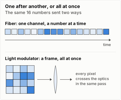
The panel itself is slow to change, from about 60 frames a second for an ordinary LCD to tens of thousands of on/off patterns a second for a mirror chip (TI's DLP7000 is rated at about 32,500). So the speed isn't in how fast one number changes. It's in how many numbers go through together and how little happens to each of them on the way.
Multiplying is the hard part
Adding is what light does by itself. Two beams from the same laser that land on the same spot add as fields. Multiplying is harder: in ordinary materials beams pass through each other without one changing the other, so you can't just cross two beams and get their product. Getting light to multiply light takes a nonlinear crystal and a lot of power.
The easy place to get a product is transmission. Put two LCD panels in a row. Light that gets through a fraction a of the first and then a fraction b of the second leaves with a·b. Put the input vector x on the first panel, copied down every row, and the weight matrix W on the second, one output per row. The light leaving is the whole grid of products Wₘₙ·xₙ at once.
That's a grid, not an answer. A dot product needs each row added up, and that's the job of a lens. A cylindrical lens focuses each row onto one spot, where its light adds, so spot m holds Σₙ Wₘₙ·xₙ. Multiply with two panels, add with a lens.
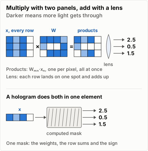
Panels like these only set how much light gets through, so every number is non-negative unless another element flips the phase for the negative ones. A hologram does both jobs in one piece: its gratings weight each input, which is the multiply, and send the matched light into one direction where it adds, which is the merge. The rest of this post is how that works, first the way the 1990s storage groups did it and then with a computed hologram that holds a whole matrix.
What a hologram stores
A hologram is a recording of two beams from the same laser crossing inside a light-sensitive material. Call the two light fields at the material R (the reference, usually a plain tilted beam) and S (the signal, which carries the data). A light field has an amplitude and a phase, so it's a complex number at each point. Recording materials respond to intensity, the squared magnitude of the total field:
|R + S|² = |R|² + |S|² + R*S + RS*The star means complex conjugate. The first two terms are each beam's own brightness. The last two are interference fringes, bright and dark stripes whose position depends on the relative phase of the two beams. If the material changes its refractive index in proportion to the exposure, the fringes become a grating frozen into it, and that grating records the signal relative to the reference.
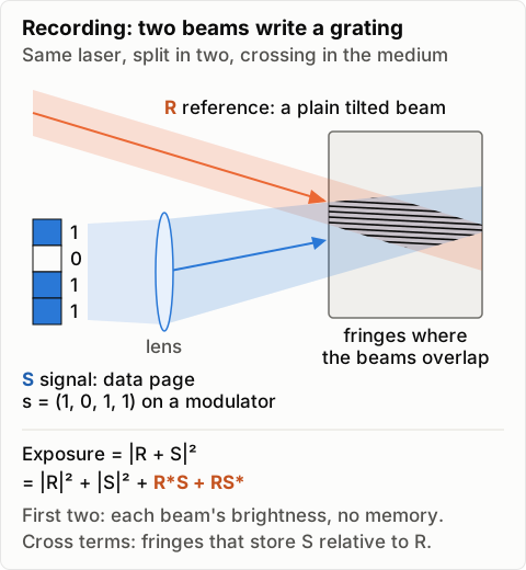
To store a vector, put the data on a spatial light modulator (a small display that imprints a pattern on a laser beam), with a lens between it and the material. The lens turns each pixel position into a direction, so pixel j becomes a plane wave travelling in direction kⱼ with amplitude sⱼ. Each pixel interferes with the reference and writes its own sinusoidal grating, oriented by the difference between the two directions and with strength proportional to sⱼ. The hologram is a sum of N gratings, one per vector entry, overlapping in the same volume.
Why reading it gives an inner product
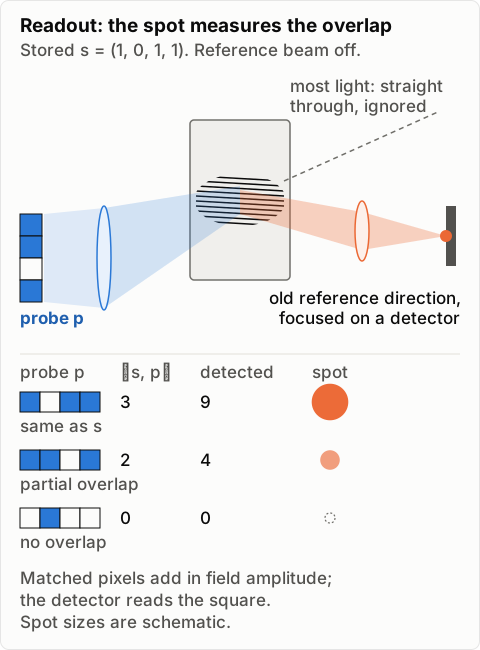
Now turn the reference off and shine a different vector p through the same modulator. Light from probe pixel i hits all N gratings. A grating deflects light by adding its own spatial frequency to the incoming wave's, so the grating written by pixel j sends pixel i's light in direction kᵢ − kⱼ + k_R. When i = j, that's exactly the old reference direction k_R. Every matched pair puts light into that one direction with amplitude proportional to pⱼ sⱼ*, and since it's all one coherent laser, the contributions add as fields:
E along k_R ∝ Σⱼ sⱼ* pⱼ = ⟨s, p⟩Put a lens after the material and a detector where the reference direction comes to a focus, and the light landing there is the inner product of the stored vector and the probe. (That assumes weak gratings, the normal case once many share a volume.)
The mismatched pairs go elsewhere. In a thin hologram they land around the central spot and fill in the rest of the cross-correlation of the two patterns: the matched filter VanderLugt described in 1964, derived in Goodman's Introduction to Fourier Optics. Its center, at zero shift, is the inner product. In a thick ("volume") hologram most mismatched pairs also miss the Bragg condition (below) and come out dim.
IBM's holographic storage group put it plainly: "The center of each correlation peak represents the 2D inner product (the simple overlap) between the input page being presented to the system and the associated stored page" (Ashley et al., IBM J. Res. Dev., 2000).
A toy example
Say the stored page is s = (1, 0, 1, 1) and the probe is p = (1, 1, 0, 1), as on/off pixels. The pixelwise products are (1, 0, 0, 1): two matched pixels each put one unit of field into the reference direction, they add to amplitude 2, and the detector sees intensity 4. A probe identical to s gives amplitude 3 and intensity 9. A probe with no lit pixels in common, (0, 1, 0, 0), gives nothing.
Two details matter in practice. First, the detector measures intensity, so you read |⟨s, p⟩|², not ⟨s, p⟩. For non-negative data you take the square root, as IBM did. Signed values are harder. A −1 is a pixel with its phase flipped by half a wave, so s = (1, −1, 0, 0) against p = (1, 1, 0, 0) cancels to a dark spot, which is correct. But −2 and +2 both read as intensity 4. Getting the sign back means interfering the result with a known reference field, or splitting positive and negative parts into separate holograms and subtracting electronically. Second, every hologram diffracts with a slightly different efficiency, so real systems calibrate each one.
The 1990s way: one hologram per row
The holographic storage groups turned this into a matrix-vector product by multiplexing. A thick hologram only diffracts efficiently when light arrives at the angle and wavelength it was recorded with. That's the Bragg condition, and Kogelnik's coupled-wave theory gives its exact shape. So you can record M different pages s⁽¹⁾…s⁽ᴹ⁾ in the same volume, each with the reference beam at a slightly different angle, and they barely interact. Mok stored 5,000 holograms in one crystal this way in 1993.
Read the whole stack with one probe p and every hologram reconstructs its own reference beam at once, each with amplitude ⟨s⁽ᵐ⁾, p⟩. A lens focuses each reference direction to its own spot on a camera, so one exposure gives
yₘ = Σⱼ sⱼ⁽ᵐ⁾* pⱼ, m = 1 … MThat's a matrix-vector product, y = S*p, with the stored pages as the rows of S. In Psaltis and Mok's words, each spot's brightness "is proportional to the degree of similarity between the input image and each of the stored patterns" (Scientific American, 1995). It works the other way too: illuminate with several reference beams at once, with amplitudes xₘ, and the camera sees Σ xₘ s⁽ᵐ⁾, the product with the transpose. Psaltis, Brady, Gu and Lin used holograms like this as the connections of an optical neural network in 1990.
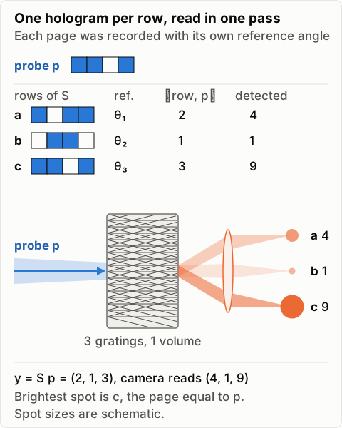
IBM built a working version as a database search: 100 holograms in one crystal, each a record with 64 analog fields holding an image's color histogram. A query lit up 100 correlation spots, and the system ranked them and read back the top eight records the normal way (Ashley et al., 2000; Burr et al., Applied Optics, 1999). They projected that video-rate parts could search a million 1 KB records in about 30 ms, versus about 40 s to scan them from a disk of that era.
This is the version most of the literature describes, and it was built for search. Every row of the matrix is its own recording, made in its own exposure. All the rows share one piece of material, so ten times as many rows means each one diffracts about a hundred times less light (more on that below). And the answers land on a camera as brightness, so the sign is gone unless you add more machinery. For a fixed weight matrix whose output should feed the next layer, there's a more direct way.
One computed hologram for the whole matrix
A hologram doesn't have to be recorded from two real beams. Since Lohmann and Paris in 1967, people have computed the fringe pattern and written it directly, with a plotter then and a laser or lithography writer now. Once you're computing the pattern, you can pick one that holds the whole matrix W in a single thin mask, read in one shot, with no per-row recordings.
The trick is to give the inputs and the outputs different axes. Send the input vector x in as N plane waves tilted left-right, entry n at tilt step n. Give output m its own up-down tilt, m steps. Then write a mask with the pattern
h(u, v) = Σₘ Σₙ Wₘₙ · exp(i(m·v − n·u))where u and v are the horizontal and vertical positions across the mask, scaled to radians. Every coefficient Wₘₙ gets its own grating: n steps left and m steps up.
Shine x through it. Input wave n passing through the grating for Wₘₖ comes out tilted n − k steps sideways and m steps up. A lens after the mask sorts the light by direction, and a slit keeps only the light with no sideways tilt, which is exactly the matched pairs, n = k. At height m along the slit, all N matched terms land together and add as fields:
light at output m ∝ Σₙ Wₘₙ xₙ = (Wx)ₘIt's the same rule as the single inner product above: matched pairs go to one direction, everything else goes somewhere else. Compared with the two panels and a lens, the mask is the weight panel and the row-summing lens in one element. The difference is that every output gets its own spot along the slit, and each spot holds a field rather than a camera reading. A negative output is light with its phase flipped, and it can go straight into the next optical stage.
The two axes matter. If inputs and outputs shared one axis, coefficient (m, n) would sit at tilt m − n, and every pair with the same difference would share one grating. That mask can only do a convolution, a matrix whose diagonals are constant. With inputs on one axis and outputs on the other, every coefficient gets a direction of its own, so W can be any matrix, signed or complex.
A simple transparency can't hold a complex number; it only transmits between 0 and 1. The fix is the same expansion as the recording at the top of this post. Add an offset and a tilted carrier:
t(u, v) = ½ + ½ · Re[ h(u, v) · exp(i·c·u) ] / h_maxwhere h_max is the peak of |h| and c is a carrier tilt larger than the spread of the inputs. The ½ plays the part of |R|² + |S|², and the real part holds the two cross terms. The copy you want comes out shifted sideways by c, clear of the offset and of its mirror image, so the slit moves to tilt c. It's an off-axis hologram whose reference beam only exists in the arithmetic.
A 2×2 check: W = [[1, 1], [1, −1]] and x = (2, 3), so Wx = (5, −1). The peak of |h| is 2√2, and the real mask puts (5, −1)/(8√2) ≈ (0.442, −0.088) on the two output spots, the second with its phase flipped. A 64×64 discrete Fourier transform of the mask matched that to rounding error. About 1/64 of the input light ends up in the answer, −18 dB.
That loss is the price. A passive mask can't transmit more than all the light at its brightest point, so the pattern has to be scaled until its peak fits, and on average that leaves at most 1/N of the input light in the answer for an ideal complex mask, and 1/(16N) for the simple real one. At N = 128 that's −21 dB and −33 dB before any other loss. The mask also needs room for N × M separately resolvable gratings: a 128×128 matrix in a 2 mm square with green light needs fringes down to about 5 µm and a lens with a numerical aperture around 0.11. And the weights are only as accurate as the writer's grayscale and placement.
Pages as tiles of a bigger matrix
A real layer has thousands of inputs and outputs, millions of coefficients, which is more than one mask holds comfortably. So cut W into blocks and make each block its own page.
With W cut into a grid of tiles, the input vector splits into matching groups x₁, x₂, x₃, and each group is copied to every tile in its column. Each page is a small computed hologram of one tile and puts out a block of partial sums. Pages in the same row of tiles feed the same outputs, so their partial sums are combined as fields, from one laser with the phases held fixed, into the final outputs. Every page is lit in the same shot; nothing is read in sequence.
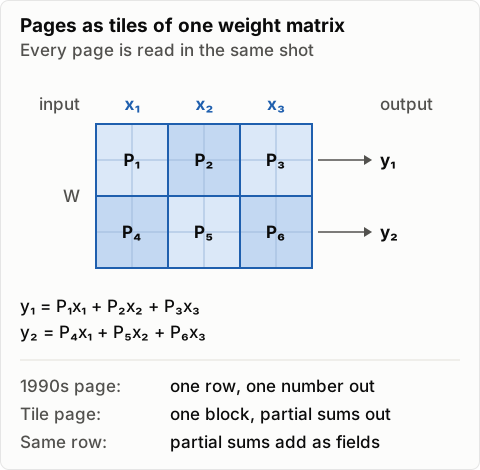
That's a different meaning of "page" from the 1990s systems. There a page was one row of the matrix and gave one number. Here a page is a block of the matrix and gives a block of partial sums. The pages can sit side by side on separate patches of film, and then each has its own dynamic range instead of splitting one crystal's. Or they can be stacked in one volume at different angles, which saves space and brings the shared budget back.
Tiling doesn't create light. Copying each input group to every row of tiles splits its power, and combining partial sums from different pages costs the same as combining terms inside one mask, so the useful fraction still falls roughly as 1 over the number of inputs. What tiling buys is smaller pieces: each page is easier to write, align, calibrate and replace, and a bad page costs one tile rather than the whole layer.
What limits it
- Bragg selectivity cuts both ways. For a thick, angle-multiplexed grating, the angular window is roughly the fringe spacing divided by the thickness: about a milliradian for 1 µm fringes in 1 mm of material. That's what lets thousands of holograms share one volume, but a little shrinkage, a temperature change or a bumped mount detunes everything too. It also means a volume correlator only sees shifts along one axis; IBM notes that only a single slice through the 2D correlation survives.
- Dynamic range is shared. Every hologram in the volume uses up part of the material's finite index change. Mok, Burr and Psaltis captured this as M/#: each of M holograms diffracts about (M/# ÷ M)² of the light, where M/# is a property of the material and setup. Ten times as many holograms means a hundred times less light from each one. This is the main cost of storing one row per hologram; pages on separate patches each get their own budget.
- Light budget. A computed mask keeps on average at most 1/N of the input light in the answer, and tiling doesn't change that. A stack of layers has to make the light back up somewhere.
- Crosstalk. Neighboring holograms leak light into each other's spots, the |S|² term writes extra gratings between pixels of the same page, and the material scatters. All of it lands on the outputs as error.
- Readout noise. Sooner or later the answer is an analog light level on a detector, with shot noise, detector noise and calibration error. IBM averaged eight frames per search and calibrated "by hologram strength". In some rewritable crystals, reading also slowly erases the hologram.
- It's analog. You get a few bits of precision, not 32. That's fine for "which stored item is most similar," which is what the old systems did, and much harder for exact arithmetic. I measured how much percent-level noise a small language model tolerates in a separate post.
- Writing is slow. Recording needs controlled exposures, and many materials need a development or fixing step, so holograms suit templates that rarely change. Fixed weights are exactly that: a computed mask is written once, offline.
Where it's already in products
This is what I could verify. The physics is the same in all of them, but only some compute a dot product of data.
- Volume Bragg gratings. A VBG is a hologram of two plane waves, usually recorded in photosensitive glass. OptiGrate (now IPG Photonics) and Ondax (now Coherent) sell them to lock laser diodes to one wavelength, as ultra-narrow notch filters for Raman spectroscopy (Ondax's modules cut the laser line by more than OD 8), and as chirped gratings that stretch and compress ultrashort pulses (RP Photonics overview). In dot-product terms a plain VBG is the smallest case: the stored vector is one plane wave of one color, and the diffracted light measures how much of the incoming beam matches it in angle and wavelength. It's a real inner product against a trivial template, and by far the most commercially successful use of this physics.
- Wavelength-selective switches in telecom networks. The reconfigurable add-drop multiplexers (ROADMs) that route wavelengths through fiber networks are built around wavelength-selective switches, mostly LCoS or MEMS based. In an LCoS switch, a grating spreads the channels across a liquid-crystal-on-silicon phase panel, which displays a computer-generated hologram, essentially a blazed grating, for each channel to steer it to an output fiber (Baxter et al., OFC 2006; review). Coherent's (formerly Finisar's) WaveShaper instruments are built on an LCoS engine too. The inner product shows up at the output: the power coupled into a single-mode fiber is the squared overlap integral of the arriving field with the fiber's mode (RP Photonics on mode matching), and one way these switches attenuate a channel is to steer it slightly off that mode on purpose. So the switch uses an inner product as a dimmer; it doesn't compute anything with your data.
- Optical correlators. Optalysys launched the FT:X 2000, a PC-attached optical correlator built on two phase-only spatial light modulators, which an EU weather-code project benchmarked. It's the thin-hologram version: the filter is displayed on a modulator rather than recorded in a volume, the correlation plane's central value is the inner product, and there's no multiplexing.
- Holographic memory as a search engine. According to Psaltis and Mok's 1995 article, their startup Holoplex built a holographic memory holding up to 1,000 fingerprints for a door lock, a device Hamamatsu was developing. That's the closest thing I found to a commercial volume-holographic inner-product machine, and I couldn't confirm it was ever sold. InPhase announced shipments of its Tapestry holographic drive in 2007 and filed for Chapter 11 in 2011, but that was an archive drive read by address. I found no sign of a commercial drive with the search mode.
- Free-space optical matrix-vector multipliers. Lumai's Iris servers do LLM matrix-vector products with light, but not with holograms. As EE Times describes it, a lens spreads the input vector across a display whose pixel transmissions hold 8-bit weights, and a second lens sums each row onto a detector: the panel-and-lens picture from the start of this post. That's one inner product per row, computed by attenuation and focusing rather than diffraction from a recorded grating. The energy and speed claims are the company's own; I haven't seen independent measurements.
What I took from it
- Light is good at this because a modulator puts a whole frame of numbers in the beam at once. Adding is free; multiplying takes a transmission or a grating.
- The inner product comes straight out of interference.
- The 1990s systems stored one row per hologram and read the rows as a similarity search. Their row count is limited by the material's shared dynamic range, and a camera reads intensity, so the sign is lost unless you design for it.
- A computed hologram can hold a whole matrix in one mask if the inputs and outputs use different axes, and its outputs are signed fields that can feed the next stage. Pages then become tiles of a bigger matrix rather than rows. The cost is light: on average at most 1/N of it reaches the answer.
- Commercially, the physics is mostly in filters and switches. The systems that computed with it did similarity search, finding the best match among many rather than doing exact arithmetic.